Parking sensor made with HC-SR04 and Raspberry
Parking sensor
In today’s article, we are going to build a parking sensor. Most of you are for sure familiar with that beeping sound in your car that starts every time you start to back your car and tells you, by changing the beeping frequency, how far your rear spoiler is from the closest obstacle. If you are not, I have just described to you what a parking sensor is. We will build a simple circuit with Raspberry Pi and HC-SR04 ultrasonic range sensor, that will simply beep according to how far it is from an obstacle. No beeping will tell us that everything around us is far away. Slow beeping will start as we will be getting closer and the closer we will be the higher will the beeping frequency be. At last, our sensor wil will beep constantly as we reach dangerously close position to our obstacle.
Distance sensor HC-SR04
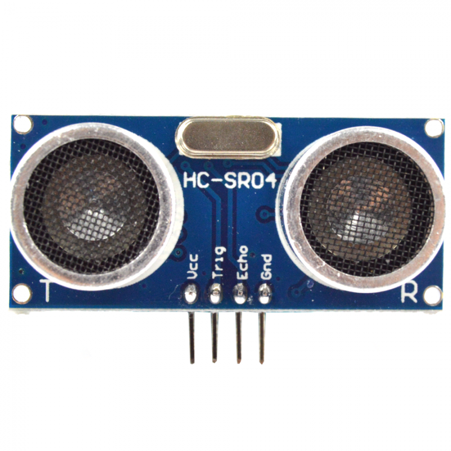
HC-SR04 is an ultrasonic range sensor. I have already written an article about JSN-SR04T sensor, which is also an ultrasonic range sensor, so if you want to know how exactly such a sensor works, go ahead and read the other article, and then come back here for the rest of the tutorial. But in a nutshell - an ultrasonic sensor has two membranes (those two tubes on HC-SR04). One sends a sound wave (on a high frequency, so we do not hear it), which travels to an obstacle, where it is reflected back to the sensor, where the second membrane registers it as it comes back and immediately sets one of its output pins to HIGH value. To measure the distance, we just take the time between sending the wave and receiving it, divide it by two, because it had to travel there and back and since we know how fast sound travels, we can compute how far the obstacle is.
HC-SR04 can measure distances from 2cm to 4 meters in angle up to 15 degrees and needs at least 5V to operate. When doing consecutive measurements, we should always wait at least 60ms between two of them, in order to reduce interference that could be caused by too many signals travelling there and back.
Connecting it to Raspberry
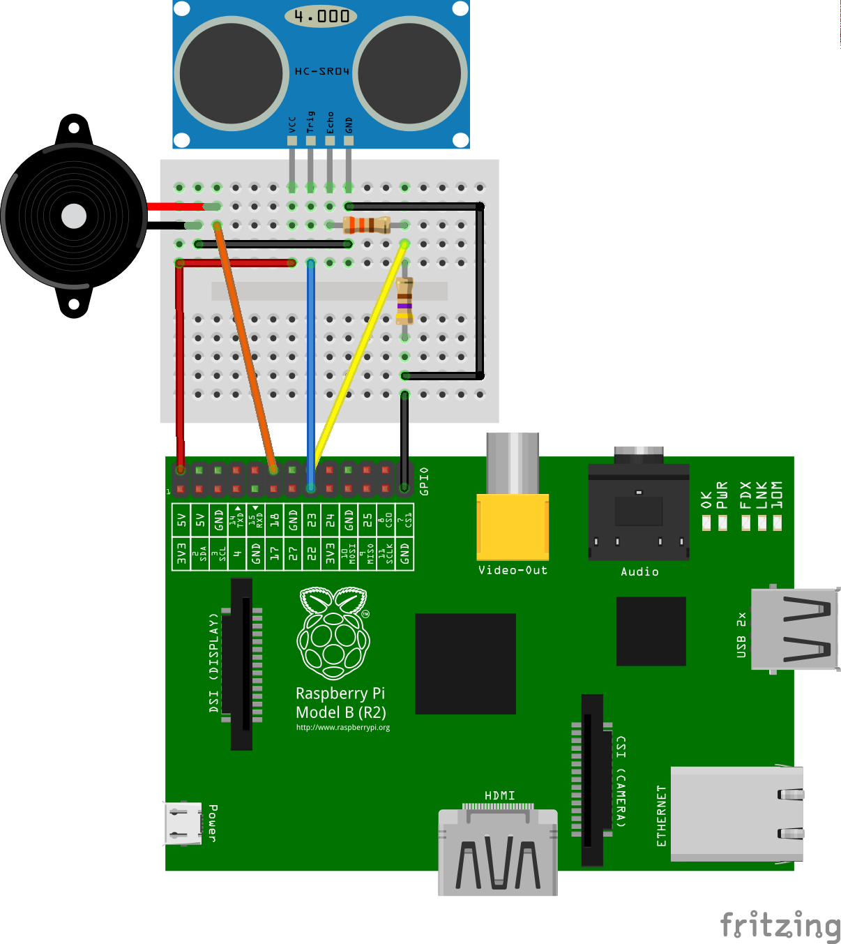
HC-SR04 has 4 pins, VCC which needs to be connected to 5V input, GND that has to be connected to ground and then two control pins TRIGGER and ECHO. In order to make the sensor send a sound wave, we need to send at least 10µs long HIGH pulse to TRIGGER pin. That means we will connect the pin with a GPIO, set it to OUTPUT mode and instruct Raspberry to set the GPIO to LOW, then very shortly to HIGH and back to LOW. At the point, when TRIGGER will switch from HIGH to LOW, the sensor will send a sound pulse. The second pin - ECHO is always in LOW, except for the moment, when it registers incoming sound wave, then it will shortly rise to HIGH. ECHO therefore needs to be connected to a GPIO set to INPUT mode, where we will be waiting for it to jump to HIGH. So far it seems like a straightforward and easy setup, but there is one catch. We can not connect ECHO pin directly to GPIO. ECHO in HIGH state gives 5V which is too high for Raspberry and could damage it. Raspberry operates with 3,3V as HIGH value, so we need to reduce the voltage coming from ECHO.
Voltage Divider
But worry not, reducing voltage from higher value to a lower one is very easy and we will only need two resistors. Lets take 330Ω and 470Ω. Put 330Ω resistor between ECHO output and GPIO, then 470Ω resistor between ground and the point where 330Ω resistor meets the GPIO connection. See the the complete circuit schema below for better understanding.
The thing we just build with resistors is called a voltage divider. 5V coming from the source will be divided on resistors, serially connected, according to their resistance ratio, which is in our case 330:470. To better understand how exactly voltage divider works, lets ignore the rest of the Raspberry circuit and just see the resistors as is illustrated on the image below.

Vin is our 5V source. Vout is the place between resistors, from where we will be taking the lowered voltage for GPIO input. Ground is obviously the last end of circuit marked with shrinking lines. Resistors are marked as Z1 and Z2. If you remember Ohm’s law, which is the cornerstone of electronics, it says that voltage is equal to resistance multiplied by current.
U = R * I
We also know, that if all the parts of circuit are in a series, which is our case, the current flowing through them will be the same. And last important thing - in serial circuit the total resistance is the sum of resistance of all resistors. Taking all of this into account, we can count the current flowing through the circuit.
From
U = R * I
we see that
I = U/R
which is
I = U/(Z1+Z2)
Putting the known numbers to equation we get that
I = 5/800 = 0.00625A = 6.25mA
OK, we have the current value, so now we can count what voltage is on each of the two resistor. Keep in mind that voltage is always measured between two points in circuit. Measuring voltage on Z1 equals to measuring voltage between Vin and Vout.
Take again Ohm’s law
U = R * I
now we know
I = 0.00625A
and
R = Z1 = 330Ω
so
Uz1 = 0.00625 * 330 = 2.0625V
And lets do the same with the second resistor, measuring voltage between points Vout and ground will give us
Uz2 = 0.00625 * 470 = 2.9375V
We can check that our calculations are correct by adding those two voltage values together. They will give us 5V so we see that no voltage disappeared and really divided according to value of resistors. All right, so the voltage got divided, now only the last step. Which of those values will be the voltage on Vout? Well, voltage is always measured against ground, so the correct answer is 2.9V - the voltage between Vout and ground which is equal to our Uz2. This might be a bit counter intuitive if you think of a current flowing from the source, where we have 5V, down to the ground, where it might be tempting to see it as it will partially ‘leak’ on Vout, so you would think the voltage between Vin and Vout is the correct answer, but no. Always remember that voltage is a value that is measured between two points, where one is ground. If you don§t believe me, just build the circuit and measure it…
Also, you might be thinking - you said we need 3.3V, but we have 2.9V, why such a weird number. Well, we could easily deduct, that to get 3.3V from 5V we would need a resistors with 1:2 ratio, so lets say 1000Ω and 2000Ω, but the most common resistors usually don§’ have this exact value, so we are using the closet we have in this case 330Ω and 470Ω, which gives us 330:470 = 1:1.42 ratio, which is close enough.
Raspberry’s input GPIO doesn’t necessarily need 3.3V to turn to HIGH state, in fact Raspberry will take anything between 1.3V and 3.3V as HIGH and anything between 0V and 0.8V as LOW, which is great, because we don’t have to be that precise when building our circuits.
Buzzer
Last part of our circuit will be a buzzer. It is a simple electronic component, that simply beeps if it is connected to the source and it is silent when it is disconnected. We will use it to acknowledge the “driver” of an approaching obstacle. Buzzer comes it many variants, be sure to buy one that is made for 3.3V voltage that our Raspberry GPIO gives us when it is in HIGH state. Connect the buzzer to a GPIO set to OUTPUT mode and to the ground.
Coding the sensor
Now lets create a file called parking_sensor.py and write a function distance, that will measure how far the obstacle is from the sensor. It will be similar to the code from article about JSN-SR04T:
#!/usr/bin/python

# Import required Python libraries
import RPi.GPIO as GPIO
import time

# We will be using the BCM GPIO numbering
GPIO.setmode(GPIO.BCM)

# Select which GPIOs you will use
GPIO_BUZZER = 18
GPIO_TRIGGER = 23
GPIO_ECHO = 22

# Set BUZZER to OUTPUT mode
GPIO.setup(GPIO_BUZZER, GPIO.OUT)
# Set TRIGGER to OUTPUT mode
GPIO.setup(GPIO_TRIGGER, GPIO.OUT)
# Set ECHO to INPUT mode
GPIO.setup(GPIO_ECHO, GPIO.IN)

# Measures the distance between a sensor and an obstacle and returns the measured value
def distance():
  # Send 10 microsecond pulse to TRIGGER
  GPIO.output(GPIO_TRIGGER, True) # set TRIGGER to HIGH
  time.sleep(0.00001) # wait 10 microseconds
  GPIO.output(GPIO_TRIGGER, False) # set TRIGGER back to LOW

  # Create variable start and assign it current time
  start = time.time()
  # Create variable stop and assign it current time
  stop = time.time()
  # Refresh start value until the ECHO goes HIGH = until the wave is send
  while GPIO.input(GPIO_ECHO) == 0:
    start = time.time()

  # Assign the actual time to stop variable until the ECHO goes back from HIGH to LOW = the wave came back
  while GPIO.input(GPIO_ECHO) == 1:
    stop = time.time()

  # Calculate the time it took the wave to travel there and back
  measuredTime = stop - start
  # Calculate the travel distance by multiplying the measured time by speed of sound
  distanceBothWays = measuredTime * 33112 # cm/s in 20 degrees Celsius
  # Divide the distance by 2 to get the actual distance from sensor to obstacle
  distance = distanceBothWays / 2

  # Print the distance to see if everything works correctly
  print("Distance : {0:5.1f}cm".format(distance))
  # Return the actual measured distance
  return distance

# Main function
def main():
  try:
    distance()
    time.sleep(1) # Pause between measurements
  # If the program is ended, stop beeping and cleanup GPIOs
  except KeyboardInterrupt:
    GPIO.cleanup()

# Run the main function when the script is executed
if __name__ == "__main__":
    main()
If you run the script from your Raspberry
python parking_sensor.py
it will print the distance each second. That is nice, but lets add the beeping. We will write another function, that will count how fast the buzzer should beep = beeping frequency. If the obstacle is more than 50cm from the sensor, it will not beep, that will be marked by value -1. If the obstacle will be closer than 50cm, but further than 30cm, we will beep once per second - value returned will be 1. If the distance will be between 30cm and 20cm, we will beep twice a second - value returned will be 0.5. For distances between 20cm and 10 cm, we will beep four times a second - value returned will be 0.25. If we will be in a dangerously close position, that is closer than 10cm to obstacle, buzzer will beep constantly - value returned will be 0. Lets put that into code.
# Calculates the frequency of beeping depending on the measured distance
def beep_freq():
  # Measure the distance
  dist = distance()
  # If the distance is bigger than 50cm, we will not beep at all
  if dist > 50:
    return -1
  # If the distance is between 50 and 30 cm, we will beep once a second
  elif dist <= 50 and dist >=30:
    return 1
  # If the distance is between 30 and 20 cm, we will beep every twice a second
  elif dist < 30 and dist >= 20:
    return 0.5
  # If the distance is between 20 and 10 cm, we will beep four times a second
  elif dist < 20 and dist >= 10:
    return 0.25
  # If the distance is smaller than 10 cm, we will beep constantly
  else:
    return 0
The only thing left is to adjust the main function to make the buzzer beep in our given frequency. We will do that by writing a simple if-else statement with result from the beep_freq function.
  # Main function
def main():
  try:
    # Repeat till the program is ended by the user
    while True:
      # Get the beeping frequency
      freq = beep_freq()
      # No beeping
      if freq == -1:
        GPIO.output(GPIO_BUZZER, False)
        time.sleep(0.25)
      # Constant beeping
      elif freq == 0:
        GPIO.output(GPIO_BUZZER, True)
        time.sleep(0.25)
      # Beeping on certain frequency
      else:
        GPIO.output(GPIO_BUZZER, True)
        time.sleep(0.2) # Beep is 0.2 seconds long
        GPIO.output(GPIO_BUZZER, False)
        time.sleep(freq) # Pause between beeps = beeping frequency
  # If the program is ended, stop beeping and cleanup GPIOs
  except KeyboardInterrupt:
    GPIO.output(GPIO_BUZZER, False)
    GPIO.cleanup()
And that is it! The complete code is right below this paragraph and you can also get it from my Gitlab. Well done, you have just successfully built your own parking sensor. Enjoy experimenting with it!
Complete program
#!/usr/bin/python

# Import required Python libraries
import RPi.GPIO as GPIO
import time

# We will be using the BCM GPIO numbering
GPIO.setmode(GPIO.BCM)

# Select which GPIOs you will use
GPIO_BUZZER = 18
GPIO_TRIGGER = 23
GPIO_ECHO = 22

# Set BUZZER to OUTPUT mode
GPIO.setup(GPIO_BUZZER, GPIO.OUT)
# Set TRIGGER to OUTPUT mode
GPIO.setup(GPIO_TRIGGER, GPIO.OUT)
# Set ECHO to INPUT mode
GPIO.setup(GPIO_ECHO, GPIO.IN)

# Measures the distance between a sensor and an obstacle and returns the measured value
def distance():
  # Send 10 microsecond pulse to TRIGGER
  GPIO.output(GPIO_TRIGGER, True) # set TRIGGER to HIGH
  time.sleep(0.00001) # wait 10 microseconds
  GPIO.output(GPIO_TRIGGER, False) # set TRIGGER back to LOW

  # Create variable start and assign it current time
  start = time.time()
  # Create variable stop and assign it current time
  stop = time.time()
  # Refresh start value until the ECHO goes HIGH = until the wave is send
  while GPIO.input(GPIO_ECHO) == 0:
    start = time.time()

  # Assign the actual time to stop variable until the ECHO goes back from HIGH to LOW = the wave came back
  while GPIO.input(GPIO_ECHO) == 1:
    stop = time.time()

  # Calculate the time it took the wave to travel there and back
  measuredTime = stop - start
  # Calculate the travel distance by multiplying the measured time by speed of sound
  distanceBothWays = measuredTime * 33112 # cm/s in 20 degrees Celsius
  # Divide the distance by 2 to get the actual distance from sensor to obstacle
  distance = distanceBothWays / 2

  # Print the distance to see if everything works correctly
  print("Distance : {0:5.1f}cm".format(distance))
  # Return the actual measured distance
  return distance

# Calculates the frequency of beeping depending on the measured distance
def beep_freq():
  # Measure the distance
  dist = distance()
  # If the distance is bigger than 50cm, we will not beep at all
  if dist > 50:
    return -1
  # If the distance is between 50 and 30 cm, we will beep once a second
  elif dist <= 50 and dist >=30:
    return 1
  # If the distance is between 30 and 20 cm, we will beep every twice a second
  elif dist < 30 and dist >= 20:
    return 0.5
  # If the distance is between 20 and 10 cm, we will beep four times a second
  elif dist < 20 and dist >= 10:
    return 0.25
  # If the distance is smaller than 10 cm, we will beep constantly
  else:
    return 0

# Main function
def main():
  try:
    # Repeat till the program is ended by the user
    while True:
      # Get the beeping frequency
      freq = beep_freq()
      # No beeping
      if freq == -1:
        GPIO.output(GPIO_BUZZER, False)
        time.sleep(0.25)
      # Constant beeping
      elif freq == 0:
        GPIO.output(GPIO_BUZZER, True)
        time.sleep(0.25)
      # Beeping on certain frequency
      else:
        GPIO.output(GPIO_BUZZER, True)
        time.sleep(0.2) # Beep is 0.2 seconds long
        GPIO.output(GPIO_BUZZER, False)
        time.sleep(freq) # Pause between beeps = beeping frequency
  # If the program is ended, stop beeping and cleanup GPIOs
  except KeyboardInterrupt:
    GPIO.output(GPIO_BUZZER, False)
    GPIO.cleanup()

# Run the main function when the script is executed
if __name__ == "__main__":
    main()